


The TSC trolley measures track geometry. The measurement
results include values of track gauge, cant, horizontal and vertical irregularities along with the calculated gradient and twist parameters.


Track measurement
Back to the list
RAILPROFILE 3D
LASER PROFILOMETER FOR 3D SWITCH PROFILE MEASUREMENT
Railprofile 3D is a laser measuring device designed to measure turnouts. The result of the measurement is a 3D model of the measured object. The device is delivered with software that allows processing measurements, including: assembling multiple measurements into one object, generating any 2D profiles, calculating longitudinal profiles, and generating reports.
The measurement result is the 3D model of the measured object, that is exact representation of the measured object both in the lateral and transverse directions. The device is delivered with the PC software making processing of the measurement results possible, including: merging of multiple measurements into one object, generating of the arbitrarily selected 2D profiles, calculation of the longitudinal profiles, generating measurement reports.
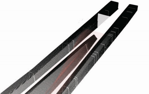
Exemplary measurement of the crossing frog. The drawing below shows the model of the measured crossing developed with 1 mm measurement increment.
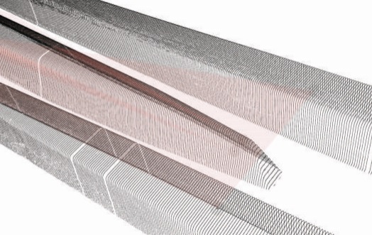
The software delivered makes it possible to recognize the particular crossing elements, i.e„ point, left and right wing rails. Based on these elements, the mathematical point of the crossing is calculated.
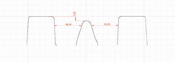
Using the 3D model, the user can acquire any transverse section profile. The section direction may be defined manually or a series of transverse sections may be generated with the particular increment along the selected virtual axis. The drawing below shows an example of the generated transverse section profile.
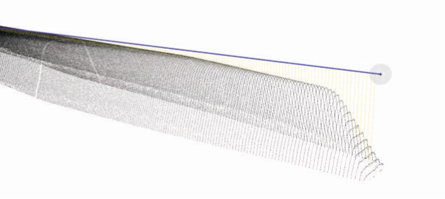
To determine the longitudinal wear of the measured elements the user may define a section (blue line below), along which the software will calculate the shape of the inspected element. This way it is possible, e.g., to determined crossing point wear in the vertical- or horizontal direction. The drawing below shows an example of the frog shape analysis.
Contents:
- Railprofile 3D devices
- Charger for the control panel
- Transport boxes
- Dari® Software for data analysis, 1 licence
Benefits:
- Accurate measurement of crossings
- Display is easy to read even in direct sunlight
- Easy transfer of measurement data via USB port
- Measurement results independent of environmental conditions
- Measured profiles can be exported as files in DXF, CSV formats
- Geolocation of point measurement using GPS on board
- Hot-swappable batteries – charged batteries at hand enable unlimited operating time
Specifications
| Profile measurement technology | Optical non-contact measurement |
| Measurement of the cross-section of the rail head and turnout | Accuracy: ±0,1 mm |
| Maximum single measurement time | 2 min |
| Measurement increment | 1 ... 10 mm |
| Fastening on the tracks | No mechanical or magnetic fixation |
| Dimensions (L x W x H) for 1435 mm track | Frame 1 800 x 610 x 240 mm |
| Measuring head 560 x 300 x 320 m | |
| Weight | Frame: 29 kg |
| Measurement head: 13 kg | |
| Memory capacity | 100 measurements |
| Operation time | Up to 8 h |
| Resolution | 0,1 mm |
| Operating conditions | Temperature: -20 ... +45 °C |
| Humidity: 15 ... 85 %, no condensation |
Gallery


Movies

Ask for product


